Civil

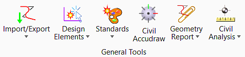
General Tools
| Settings | Description |
|---|---|
| Import/Export | Allows to import or export geometry. |
| Design Elements | Allows you to set active profile. |
| Standards | Allows you to set design standards. |
| Civil Toggles | Allows you to toggle civil accudraw and civil rules option. |
| Reports | Allows you to get reports of the elements. |
| Civil Analysis |
Civil Analysis group
|


Horizontal

| Settings | Description |
|---|---|
| Lines | Allows you to draw line between points. |
| Arcs | Allows you to place an arc. |
| Points | Allows you to place, locate, and modify points. |
| Offset and Tapers | Allows you to create offsets and tapers from element. |
| Reverse Curves | Allows you to create a reverse curve between two existing elements. |
| Spirals | Allows you to place spirals from and between the elements. |
| Modify | Allows you to modify properties of existing horizontal elements |
| Complex Geometry | Allows you to create a horizontal complex geometry. |


Vertical

| Settings | Description |
|---|---|
| Open Profile Model | Allows you to open the profile model of desired element in the selected view. |
| Set Active Profile | Allows you to set a vertical complex as the active profile. |
| Profile Creation | Allows you to generate profile complex. |
| Lines | Allows you set of different line placement tools. |
| Curves | Allows you set of different curve placement tools. |
| Element Profiles | Allows you set of vertical profile creation tools. |


Superelevation

| Settings | Description |
|---|---|
| Create | Allows you to create a superelevation section for the specified station range on the baseline reference to demarcate a stretch of roadway for superelevation calculations. |
| Calculate | Allows you to compute the station and cross slopes of transitions. |
| Edit | Allows you to insert or edit superelevation. |
| Superelevation Report | Allows you to create a superelevation XML report of stations, transitions, cross slopes, and other super data and opens the Bentley Civil Report Browser. |
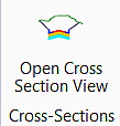
| Open Superelevation View | Allows you to open the editable superelevation diagram directly in a MSTN view. |
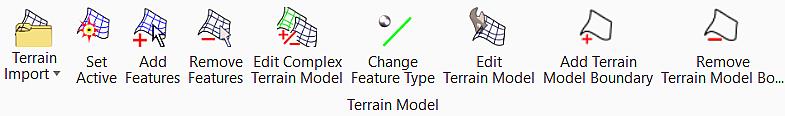
Terrain Model
| Settings | Description |
|---|---|
| Terrain Import | Allows you to import model from file. |
| Set Active | Allows you to set active terrain model. |
| Add Features | Adds more features into the terrain that was created using the create commands. Example, create the terrain from break lines, then add points. |
| Remove Features | Removes elements from a terrain which were added by Add Features or Create from Elements. |
| Edit Complex Terrain Model | Edits a complex terrain by changing the order of merging, change merge or append methods and add or remove component terrain models. |
| Change Feature Type | Allows you to update the existing features. |
| Edit Terrain Model | Edits a terrain model by changing the order of merging, change merge or append methods and add or remove component terrain models. |
| Add Terrain Model Boundary | Adds boundary to terrain model. |
| Remove Terrain Model Boundary | Removes boundary from terrain model. |


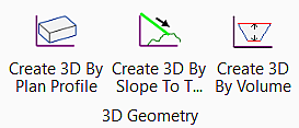
3D Geometry
| Settings | Description |
|---|---|
| Create 3D By Plan Profile | Allows you to create a 3D element from a portion of a profile line. |
| Create 3D By Slope To Target | Allows you to create a 3D element computed from a linear element to a surface. |
| Create 3D By Volume | Allows you to a terrain modeling computed by volume from another reference surface. |


